Games Port Input
The "IBM Games Port" is designed as a 'joystick' port. Two joysticks,
each with two switches and two 'paddles' (100k ohm potentiometers) may be connected via
the 15 pin socket at the rear of the machine. For our purposes, this means we have access
to four 'switched' lines and 4 'analogue to digital' lines. As an added bonus, the Games
port also provides +5 volts! (and GROUND)
This port is very safe to experiment with. All lines feed through a 74LS244 Integrated
Circuit (IC) which helps ensure reliable signals and provides a degree of protection
against "accidents".
| PIN NUMBER |
FUNCTION |
| 1 |
+5 Volts |
| 2 |
Button 4 (Switched) |
| 3 |
Position 0 (A to D) |
| 4 |
GROUND |
| 5 |
GROUND |
| 6 |
Position 1 (A to D) |
| 7 |
Button 5 (Switched) |
| 8 |
+5 Volts |
| 9 |
+5 Volts |
| 10 |
Button 6 (Switched) |
| 11 |
Position 2 (A to D) |
| 12 |
GROUND |
| 13 |
Position 3 (A to D) |
| 14 |
Button 7 (Switched) |
| 15 |
+5 Volts |
|
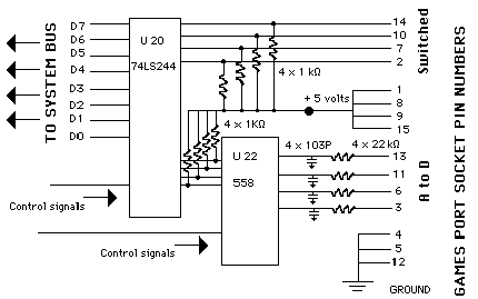
Games Port Schematic
(See below for the PCB
design for an Interface.) |
NOTE: All the "+5 Volts" lines and all the
"GROUND" lines are connected internally. In your experimenting, you need only
connect to ONE of each.
The 'switched' inputs are tied high inside the computer using 1K resistors connected to
the 5 volt rail. An external switch is used to switch directly to GROUND. No other
current-limiting circuitry is required. You could, in fact, use two lengths of wire pushed
into the port and simply touch the bare ends together. (This is, after all, the way a
'switch' works!)
Reading the Games Port:
Switched Input
The four 'switched' lines may be read using a standard <IN address 512> command.
In Pascal this would be: InValue := port[512].
In MSW Logo it would be: make "InValue InportB 512
A to D Sensors:
The four 'analogue' lines available at the Games Port offer exciting possibilities.
These lines allow conversion of the value of an external resistance into digital form
which the computer can manipulate. The resistance may be from 0 ohm to 100k ohm. If you
wanted to, you could simply push the legs of a Light Dependant Resistor (LDR) into the
appropriate pin holes at the games port and "read" the change in light intensity
falling on the LDR. ( I certainly don't endorse the procedure, but the port is
sufficiently robust to take this type of treatment.)
A better approach is to use an external 'adapter' board connected to the computer via
ribbon cable. (See below ...)
How the A to D function works:
When an output command is issued to the Games Port, a "control signal" is
sent to the port and a digital pulse is generated on each of the four output lines of IC
U22 (558). The lines remain HIGH for a time determined by the value of the external
resistance connected to each respective input line of IC 558.
The data pulse (HIGH) produced on each of the lines of the 558 remains high for a duration
determined by the value of the external resistance, according to:
Time = 24.2 micro sec + 0.011 (R) micro sec (R is ohms)
The state of lines D3 to D0 are then read using INP(512). (Where 512 is the digital
'address' of the analogue input lines.) The programmer must therefore produce a
"looping" routine to determine the duration of each pulse. As can be seen by the
formula, the maximum pulse length for a 100k ohm resistor is:
24.2 microsec + 11000 microseconds = 11,024.2microseconds
If you want accurate timing, your "loop" routine will need to be very
fast! For most applications, even a Pascal routine will be too slow.
A to D conversion
The 'control signal' referred to above is:
Pascal - Port[512] := <any value>
The sequence for reading the 'A to D' lines therefore becomes:
- Send the control signal. (<out 512>)
- Read the port.
- Set up a counting LOOP until each line goes LOW.
- Interpret the 'count' as a resistance value.
A typical Pascal Input routine would be:
repeat
count := 0;
Port[512] := 1;
repeat
PortByte := Port[512];
count := count + 1;
until (PortByte AND 4 = 0);
writeln(count);
until KeyPressed;
|
{Start the main loop.}
{Initialises the loop counter.}
{Starts the 'A to D' process. Any value would do.}
{Start the counting loop.}
{Reads the Games Port.}
{Increments the count.}
{Tests to see if D2 is still HIGH - ie pin number 4.}
{Writes the value of "count" to screen.}
{The main loop stops when a key is pressed.}
|
Having obtained a 'count' for a data line, the software must then relate this 'raw'
value to resistance.
NOTE: The example given above examines only ONE of the
four data lines. If you want simultaneous conversion of all lines, you would need
to 'AND' "PortByte" with 1, 2, 4 and 8, while 'counting' during the HIGH state
of each!
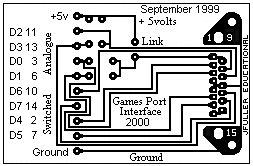
A Games Port
Interface
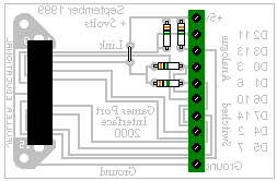
The Games Port is sufficiently protected to avoid the necessity
of additional electronic 'interfacing'. Its location at the rear of the system does
however make it inconvenient for experimenting. The PCB below may be used to provide easy
access. You will also need a "Joystick Extension Cable" which consists of a
straight-through lead with a Male connector on one end and a Female connector on the
other.
PartList
- 1 x DB15 Male PCB Socket
- 5 x 2-way PCB Terminals
- 1 piece of 'link' wire
- 1 x Joystick Extension Cable
- 4 x 100K to 1M 1/2 watt carbon resistors |
 |
 |
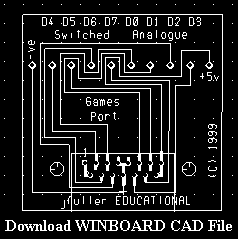
An alternate PCB design for WINBOARD users.
ANDing
When you read the Games Port with Pascal - InValue := Port[512], or MSW Logo
- Make "InValue InportB 512 you will return a number for "InValue" that
represents the TOTAL value of the input lines. To be able to decode which individual line
is turned on you must understand the concept of "ANDing". MSW Logo refers the
process as "BitAnd".
Imagine each data line is represented by the little globes in the diagram below. The
'screen' in front of the globes represents the data values we want to "AND" with
the globes. An "ON" globe represents a "1" and a hole in the screen
represents a "1".
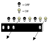
This example could be represented by : 00101011 AND 11100001. The result of
ANDing these two binary numbers is: 00100001. If they are written under each other
it may be a little easier to see:
00101011
AND
11100001
is ...
00100001
If two corresponding values in the binary numbers are "1" the
value in the result will also be "1". It is also said that the result of this
ANDing is "TRUE" for bits one and six.
When dealing with decimal numbers it is not quite as obvious, but the same principle
applies. eg 01000000 AND 64 is TRUE, 10001001 AND 8 is TRUE. 10001001 AND 128 is TRUE,
10001001 AND 1 is TRUE.
The typical code to decode an individual line at the Games Port in MSW Logo would be:
to DecodeLine
make "Line8 [OFF]
make "InValue inportb 512
make "result BitAND :InValue 128
test :result = 128
iftrue [make "Line8 [ON]]
label :Line8
end
More information about the Games Port can be found at:
http://www.2xtreme.net/dage/index.html
http://www.jadesys.demon.co.uk/ir-part5.htm
<- Back


